
Product Description
This FY•X advanced 20S 72V 15A Hardware BMS for E-Unicycle is a protective plate solution specially designed by Wenhong Technology Company for unicycle 20-string battery packs; it can be applied to different chemical propertiesLithium batteries, such as lithium ion, lithium polymer, etc. The protection board has strong load capacity, and the maximum continuous current can be 15A.
FY•X advanced 20S 72V 15A Hardware BMS for E-Unicycle Functional characteristics
● 20 batteries are protected in series;
● Charging and discharging voltage, temperature and other protection functions;
● Discharge alarm function;
● The switch controls the on/off function.
● Extremely low static power consumption.
● There is no discharge overcurrent and short circuit protection function. If overcurrent or short circuit occurs at the discharge port, the protection board may be burned out.
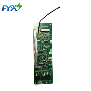
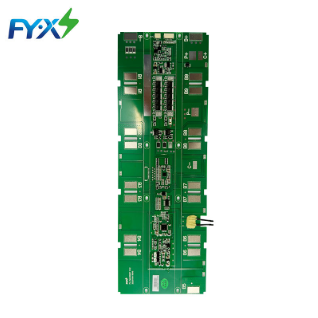
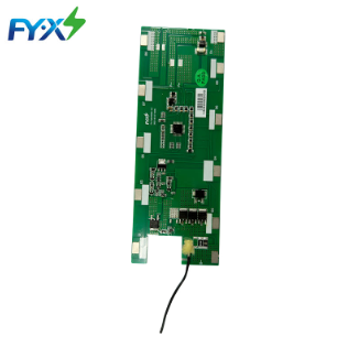
Physical reference picture

Figure 1: BMS front view
Figure 2: Physical picture of the back of BMS
Electrical Characteristic (Ta = 25 ℃.)
| Details | Min. | Typ. | Max | Error | Unit | ||
| Battery | |||||||
| Battery Gas | LiCoxNiyMnzO2 | ||||||
| Battery Links | 20S | ||||||
| Absolute Maximum Rating | |||||||
| Input Charging Voltage | 84 | ±1% | V | ||||
| Input Charging Current | 2 | 3 | A | ||||
| Output Discharging Voltage | 56 | 72 | 85 | V | |||
| Output Discharging Current | 25 | A | |||||
| Continuous Output Discharging Current | ≤25 | A | |||||
| Ambient Condition | |||||||
|
Operating Temperature |
-20 | 65 | ℃ | ||||
| Humidity (No Water-Drop) | 0% | RH | |||||
| Storage | |||||||
| Temperature | -40 | 85 | ℃ | ||||
| Humidity (No Water-Drop) | 0% | RH | |||||
| Protection Parameters | |||||||
| Over-Charge Voltage Protection | 4.250 | ±30mV | V | ||||
| Over-Charge Voltage Protection Delay Time | 1 | -0.5/+1 | S | ||||
| Over-Charge Voltage Protection Release | 4.150 | ±50mV | V | ||||
| Over-Discharge Voltage Protection | 2.800 | ±80mV | V | ||||
| Over-Discharge Voltage Protection Delay Time | 20 | ±3 | S | ||||
| Over-Discharge Voltage Protection Release | 3.000 | ±100mV | V | ||||
| Charging Temperature | 60 | ±5 | ℃ | ||||
| Charging Temperature Protection Release | 55 | ±5 | |||||
| Discharge over-temperature alarm (only alarm, does not shut down discharge) | 65 | ±5 | ℃ | ||||
| Discharge over-temperature alarm release | 60 | ±5 | ℃ | ||||
| Current Consumption | |||||||
| SleepConsumption | 150 | 250 | uA | ||||
| ShipConsumption | 100 | uA | |||||
The above parameters are recommended values and users can modify them according to actual applications.
BMS principle block diagram
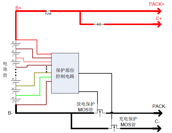
Figure 7: Protection principle block diagram
PCB and dimensional structure diagram
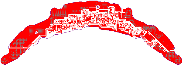
Figure 8: Motherboard top-level wiring diagram

Figure 9: Motherboard bottom wiring diagram

Figure 10: Dimensions 358.4*127 Unit: mm Tolerance: ±0.5mm
Protection board thickness: less than 10mm (including components)
Port Definition


Figure 11: Wiring diagram of the protection board
Port definition:
| Item | Details | |
| C+ | Charging Positive Port. | |
| P+ | Discharging Positive Port. | |
| B+ | Connect to Positive Side of the pack. | |
| B- | Connect to Negative Side of the pack. | |
| P- | Discharging Negative Port. | |
| C- | Charging Negative Port. | |
| B1 | Connect to Positive Side of Cell 1. | |
| B2 | Connect to Positive Side of Cell 2. | |
| B3 | Connect to Positive Side of Cell 3. | |
| B4 | Connect to Positive Side of Cell 4. | |
| B5 | Connect to Positive Side of Cell 5. | |
| B6 | Connect to Positive Side of Cell 6 | |
| B7 | Connect to Positive Side of Cell 7 | |
| B8 | Connect to Positive Side of Cell 8 | |
| B9 | Connect to Positive Side of Cell 9 | |
| B10 | Connect to Positive Side of Cell 10. | |
| B11 | Connect to Positive Side of Cell 10. | |
| B12 | Connect to Positive Side of Cell 12. | |
| B13 | Connect to Positive Side of Cell 13. | |
| B14 | Connect to Positive Side of Cell 14. | |
| B15 | Connect to Positive Side of Cell 15. | |
| B16 | Connect to Positive Side of Cell 16 | |
| B17 | Connect to Positive Side of Cell 17 | |
| B18 | Connect to Positive Side of Cell 18 | |
| B19 | Connect to Positive Side of Cell 19 | |
| CHG | CHG (charger insertion detection signal) | |
| UD | warning signal | |
| ON | ON (power-on control terminal: connect an external touch switch with a 200K resistor to B+), press the switch to discharge and output | |
| OFF | OFF (shutdown control terminal: connect an external light touch switch with a 200K resistor to B+), press the switch continuously for 30 seconds to discharge and there is no output. | |
| PG | PGND plus isolated power ground | |
| NTC | Temperature detection probe | |

Figure 12: Schematic diagram of battery connection sequence
Precautions for connecting the protective board and the battery core
Warning: When connecting the protective plate to the battery cells or removing the protective plate from the battery pack, the following connection sequence and regulations must be followed; if operations are not performed in the required order, the components of the protective plate will be damaged, resulting in the protective plate being unable to protect the battery. core, causing serious consequences.
Preparation: According to the definition shown in Figure 11, connect the corresponding voltage detection cable to the corresponding battery core. Please pay attention to the order in which the sockets are marked.
Steps to install protective board:
Step 1: Weld the P- and C- wires to the corresponding positions of the protection board without connecting the charger and load.
Step 2: Connect the negative pole of the battery pack to B- of the protection board;
Step 3: Connect B1, 2, 3, 4, 5, 6, 7, 8, 9, 10, 11, 12, 13, 14, 15, 16, 17, 18, 19 of the battery pack in sequence;
Step 4: Connect the positive terminal of the battery pack to B+ of the protection board;
Step 5: Connect the P+ of the battery pack;
Steps to remove the protective plate:
Step 1: Disconnect the positive terminal of all chargers\loads
Step 2: Remove the positive electrode of the battery pack to B+ of the protective plate;
Step 3: Remove B19, 18, 17, 16, 15, 14, 13, 12, 11, 10, 9, 8, 7, 6, 5, 4, 3, 2, 1, B of the battery pack in sequence -;
Step 4: Disconnect the negative terminal C-/P- of all chargers\loads
Additional notes: Please pay attention to electrostatic protection during production operations.
BOM list of main components
| Device type | model | encapsulation | brand | Dosage | Location | |
| 1 | Chip IC | PT6010EL32-AA | TQFP32 | China Resources Micro | 2PCS | U6,7 |
| 2 | Chip IC | N76E003AT20 | TSSOP20 | New Tang Dynasty | 1PCS | U5 |
| 3 | MOS tube | CRST045N10N | TO220 | China Resources Micro | 3PCS | M4,5,6,8 |
| 4 | PCB | Fish20S006(V8S) V1.1 | 358.4*127*1.6mm | brand | 1PCS |
Note: If SMD transistors and MOS tubes are out of stock, our company may replace them with other models of similar specifications.
Ordering information
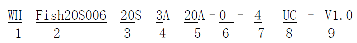
1 Huizhou Feiyu New Energy Technology Co., Ltd. logo;
2 Protection board model – (This protection board model is Fish20S006, other types of protection boards are marked, there is no limit to the number of characters in this item)
3. The number of battery strings supported by the required protection board – (this model of protection board is suitable for 17S battery packs);
4 Charging current value – 3A means maximum support for continuous 3A charging;
5 Discharge current value – 20A means the maximum support for continuous charging is 20A;
6 Balance resistance size – fill in the value directly, for example, 100R, then the balance resistance is 100 ohms;
7 Battery type – one digit, the specific serial number indicates the battery type as follows;
| 1 | Polymer |
| 2 | LiMnO2 |
| 3 | LiCoO2 |
| 4 | LiCoxNiyMnzO2 |
| 5 | LiFePO4 |
8 Communication method – one letter represents a communication method, I represents IIC communication, U represents UART communication, R represents RS485 communication, C represents CAN communication, H represents HDQ communication, S represents RS232 communication, 0 represents no communication, product UC Represents UART+CAN dual communication;
9 Hardware version – V1.0 means the hardware version is version 1.0.
10 The model number of this protection board is: WH-Fish20S006-20S-3A-25A-0-4-0-V1.0. Please place the order according to this model number when placing bulk orders.
Additional notes:
1. When performing charge and discharge tests on the battery pack with the protective board installed, please do not use a battery aging cabinet to measure the voltage of each cell in the battery pack, otherwise the protective board and battery may be damaged. .
2. This protection board does not have a 0V charging function. Once the battery reaches 0V, the battery performance will be severely degraded and may even be damaged. In order not to damage the battery, the user should not charge the battery for a long time (the battery pack capacity is greater than 15AH, and the storage exceeds 1 Months) When not in use, it needs to be charged regularly to replenish the battery; when in use, it must be charged in time within 12 hours after being discharged to prevent the battery from being discharged to 0V due to self-consumption. Customers are required to have an obvious sign on the battery casing that the user regularly maintains the battery.
3. This protection board does not have reverse charging protection function. If the polarity of the charger is reversed, the protection board may be damaged.
4. This protective board shall not be used in medical products or products that may affect personal safety.
5. Our company will not be responsible for any accidents caused by the above reasons during the production, storage, transportation and use of the product.
6. This specification is a performance confirmation standard. If the performance required by this specification is met, our company will change the model or brand of some materials according to the order materials without further notification.
Note: After your company receives the prototype and specifications, please reply promptly. If there is no reply within 7 days, our company will regard your company as having recognized the specifications and send the prototype. If your order exceeds 50 PCS, you need to sign back the acknowledgment letter. If you do not sign back, our company will also regard your company as having approved this specification and send the sample machine. The pictures in the specification are of general models and may be slightly different from the sample delivered. Huizhou Feiyu New Energy Technology Co., Ltd. reserves the right of final interpretation of this specification.
Related products
10S 36V 15A Hardware BMS for E-scooter
Model:Fish10S006