
Product Description
This FY•X 17S 60V 45A smart BMS for Battery Rental Replacement is a BMS specially designed by Huizhou Feiyu New Energy Technology Co., Ltd. for electric bicycle battery packs in the rental market. It is suitable for 17-cell lithium batteries with different chemical properties, such as lithium ion, lithium polymer, lithium iron phosphate, etc.
The BMS is equipped with a GPRS module, which can promptly report the battery pack positioning information and the corresponding voltage, current, temperature, and protection status information of the battery pack. It supports powerful functions such as remote lossless upgrade of firmware and remote locking of the battery pack.
It has a CAN communication interface that can be used to set various protection voltage, current, temperature and other parameters, which is very flexible. And the charging cabinet is identified through CAN communication. Non-designated charging cabinets cannot charge the battery pack normally. The charging cabinet is supported to upgrade the firmware function of the BMS through CAN communication without loss. The protection board has strong load capacity and the maximum sustainable discharge current can reach 35A.
FY•X 17S 60V 45A smart BMS for Battery Rental Replacement Functional characteristics
● 17 batteries are protected in series.
● Charging and discharging voltage, current, temperature and other protection functions.
● Output short circuit protection function.
●Two-channel battery temperature, BMS ambient temperature, FET temperature detection and protection.
● Passive balancing function.
● Accurate SOC calculation and real-time estimation.
● Various fault data storage.
● Protection parameters can be adjusted through the host computer.
● CAN communication can monitor battery pack information through the host computer or other instruments.
● Multiple sleep modes and wake-up methods.
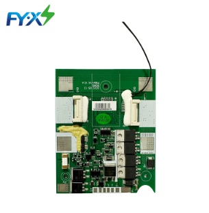
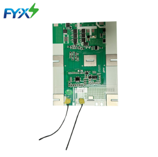
Physical reference picture
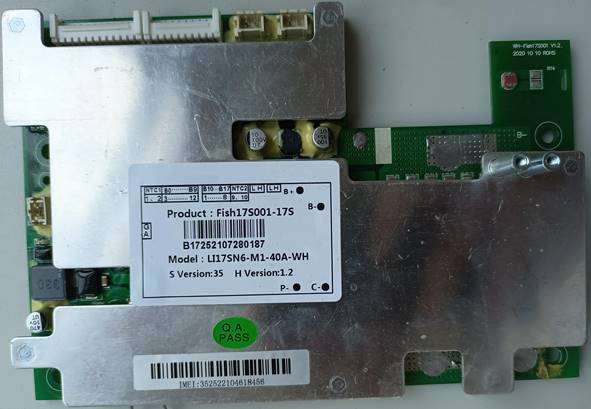
Figure 1: BMS front view, for reference only
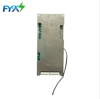
Figure 2: Physical picture of the back of BMS, for reference only
Electrical parameters(Ta = 25 ℃.)
| Specification | Min. | Typ. | Max | Error | Unit | |||||||||
| Battery | ||||||||||||||
| Battery Type | LiCoxNiyMnzO2 | |||||||||||||
| Number of battery strings | 17S | |||||||||||||
| absolute maximum ratings | ||||||||||||||
| Charging voltage input | 71.4 | ±1% | V | |||||||||||
| recharging current | 7 | 10 | A | |||||||||||
| Discharge output voltage | 51 | 61.2 | 71.4 | V | ||||||||||
| Discharge output current | 35 | A | ||||||||||||
| Sustainable working current | ≤35 | A | ||||||||||||
| environmental conditions | ||||||||||||||
| Operating temperature | -30 | 75 | ℃ | |||||||||||
| humidity | 0% | RH | ||||||||||||
| store | ||||||||||||||
| Storage temperature | -20 | 65 | ℃ | |||||||||||
| Storage humidity | 0% | RH | ||||||||||||
| Protection parameters | ||||||||||||||
| Software overvoltage protection value | 4150 | 4.200 | 4250 | ±50mV | V | |||||||||
| Software overvoltage protection delay | 1 | 3 | 6 | S | ||||||||||
| Hardware overvoltage protection value | 4250 | 4.300 | 4350 | ±50mV | V | |||||||||
| Hardware overvoltage protection delay | 2 | 4 | 7 | S | ||||||||||
| Overvoltage protection release value | 4050 | 4.100 | 4150 | ±50mV | V | |||||||||
| Software over-discharge protection value | 2.900 | 3.000 | 3.100 | ±100mV | V | |||||||||
| Software over-discharge protection delay | 3 | 5 | 8 | S | ||||||||||
| Hardware over-discharge protection value | 2.400 | 2.500 | 2.600 | ±100mV | V | |||||||||
| Hardware over-discharge protection delay | 6 | 8 | 11 | 6 | S | |||||||||
| Over-discharge protection release value | 3.200 | 3.300 | ±100mV | V | ||||||||||
| Charging overcurrent protection value | 13 | 15 | 18 | A | ||||||||||
| Charging overcurrent protection delay | 1 | 3 | 6 | S | ||||||||||
| Charging overcurrent protection release delay | Delay 30±5s to automatically release or discharge | |||||||||||||
| Software discharge overcurrent protection value | 41 | 45 | 50 | A | ||||||||||
| Software discharge overcurrent protection delay | 1 | 3 | 6 | S | ||||||||||
| Discharge overcurrent protection protection release conditions | Delay 30±5s to automatically release or discharge | S | ||||||||||||
| Hardware discharge overcurrent protection value | 115 | 130 | 150 | A | ||||||||||
| Hardware discharge overcurrent protection delay | 40 | 80 | 250 | mS | ||||||||||
| Discharge overcurrent protection release conditions | Delay 30±5s to automatically release or discharge | |||||||||||||
| Discharge short circuit protection value | 296.7 | 800 | A | |||||||||||
| Discharge short circuit protection delay | 200 | 400 | 800 | uS | ||||||||||
| Discharge short circuit protection release conditions | Disconnect the load and delay 30±5s to automatically release or charge | |||||||||||||
| Short circuit instructions | Short circuit description: If the short-circuit current is less than the minimum value or higher than the maximum value, the short-circuit protection may fail. If the short-circuit current exceeds 1000A, short-circuit protection is not guaranteed, and short-circuit protection testing is not recommended. | |||||||||||||
| 65 | 70 | 75 | ℃ | |||||||||||
| Discharge high temperature protection value | 55 | 60 | 65 | ℃ | ||||||||||
| Discharge high temperature release value | -35 | -30 | -25 | ℃ | ||||||||||
| Discharge low temperature protection value | -25 | -20 | -15 | ℃ | ||||||||||
| Discharge low temperature release value | 60 | 65 | 70 | ℃ | ||||||||||
| Charging high temperature protection value | 50 | 55 | 60 | ℃ | ||||||||||
| Charging high temperature release value | -5 | 0 | 5 | ℃ | ||||||||||
| Charging low temperature protection value | 0 | 5 | 10 | ℃ | ||||||||||
| Charging low temperature release value | ||||||||||||||
| Equilibrium parameters | 4.100 | mV | ||||||||||||
| Balanced turn-on voltage value | 4.099 | mV | ||||||||||||
| Minimum equilibrium pressure difference | 40 | mA | ||||||||||||
| Maximum equilibrium pressure difference | static equilibrium | |||||||||||||
| Equilibrium description | Turn on: The voltage difference range is turned on within the range of 25~200mV and the static balancing turn-on time does not exceed 5 hours (set to 4 hours); the current during charging is less than 1A balanced and greater than 1A unbalanced; | |||||||||||||
| Power consumption parameters | ||||||||||||||
| With GPRS power supply 4V, normal power consumption without module | 25 | 30 | mA | |||||||||||
| Whole board sleep power consumption with GPRS power supply 4V (excluding GPRS module) | 1.3(GD) | 1.5(GD) | mA | |||||||||||
| 0.52(APM) | 0.9(APM) | mA | ||||||||||||
| 0.52(ST) | 0.9(ST) | mA | ||||||||||||
| Turn off the whole board sleep power consumption of GPRS power supply 4V | 650(GD) | 1000(GD) | uA | |||||||||||
| 150(APM) | 250(APM) | uA | ||||||||||||
| 150(ST) | 250(ST) | uA | ||||||||||||
| Deep sleep power consumption | 20 | 50 | uA | |||||||||||
Note: Different chips have different power consumption. If hardware discharge overcurrent 2 protection occurs during sleep, the protection delay time will be extended by about 100ms.
The above parameters are recommended values and users can modify them according to actual applications.
BMS principle block diagram
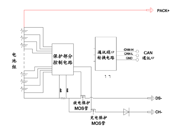
Figure 7: Protection principle block diagram
PCB and dimensional structure diagram
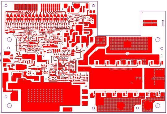
Figure 8: Motherboard top-level wiring diagram

Figure 9: Motherboard bottom wiring diagram

Figure 10: Middle layer 1 wiring diagram
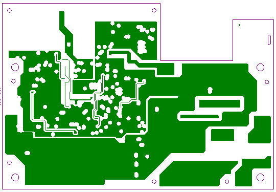
Figure 11: Middle layer 2 wiring diagram
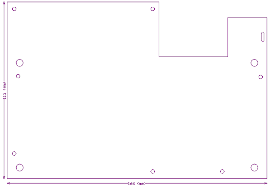
Figure 12: Dimensions 166*113 Unit: mm Tolerance: ±0.5mm
Protection board thickness: less than 15mm (including components)
Port Definition
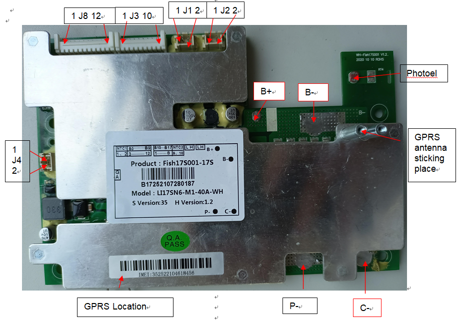
Figure 11: Protection board wiring diagram
Port definition description:
| Item | Details | |
| B+ | Connect to Positive Side of the pack. | |
| B- | Connect to Negative Side of the pack. | |
| P- | Discharging Negative Port. | |
| C- | Charging Negative Port. | |
| J1 | 1 | L CAN communication L line |
| 2 | H CAN communication H line | |
| J4 | 1 | Aging mode control switch |
| 2 | Aging mode control switch | |
| J8(Low end) | 1 | NTC(RT5)10K |
| 2 | ||
| 3 | Connect to Negative of Cell 1. | |
| 4 | Connect to Positive Side of Cell 1. | |
| 5 | Connect to Positive Side of Cell 2. | |
| 6 | Connect to Positive Side of Cell 3. | |
| 7 | Connect to Positive Side of Cell 4. | |
| 8 | Connect to Positive Side of Cell 5. | |
| 9 | Connect to Positive Side of Cell 6 | |
| 10 | Connect to Positive Side of Cell 7 | |
| 11 | Connect to Positive Side of Cell 8 | |
| 12 | Connect to Positive Side of Cell 9 | |
| J3(high-end) | 1 | Connect to Positive Side of Cell 10 |
| 2 | Connect to Positive Side of Cell 11 | |
| 3 | Connect to Positive Side of Cell 12 | |
| 4 | Connect to Positive Side of Cell 13 | |
| 5 | Connect to Positive Side of Cell 14 | |
| 6 | Connect to Positive Side of Cell 15 | |
| 7 | Connect to Positive Side of Cell 16 | |
| 8 | Connect to Positive Side of Cell 17 | |
| 9 | NTC(RT1)10K | |
| 19 | ||
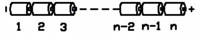
Figure 12: Schematic diagram of battery connection sequence
Precautions for connecting the protective board and the battery core
Warning: When connecting the protective plate to the battery cells or removing the protective plate from the battery pack, the following connection sequence and regulations must be followed; if operations are not performed in the required order, the components of the protective plate will be damaged, resulting in the protective plate being unable to protect the battery. core, causing serious consequences.
Preparation: As shown in Figure 11, connect the corresponding voltage detection cable to the corresponding battery core. Please pay attention to the order in which the sockets are marked.
Steps to install protective board:
Step 1: Solder the P-line to the P-pad of the protection board without connecting the charger and load;
Step 2: Connect the negative pole of the battery pack to B- of the protection board;
Step 3: Connect the positive terminal of the battery pack to B+ of the protection board;
Step 4: Connect the battery pack and battery rows to J8 on the protection board;
Step 5: Connect the battery pack and battery rows to J3 of the protection board;
Step 6: Charge and activate.
Steps to remove the protective plate:
Step 1: Disconnect all chargers\loads
Step 2: Unplug the battery pack and battery strip connector J3;
Step 3: Unplug the battery pack and battery strip connector J8;
Step 4: Remove the connecting wire connecting the positive electrode of the battery pack from the B+ pad of the protective plate
Step 5: Remove the connecting wire connecting the negative electrode of the battery pack from the B- pad of the protective plate
Additional notes: Please pay attention to electrostatic protection during production operations.
BOM list of main components
| Device type | model | encapsulation | brand | Dosage | Location | ||
| 1 | Chip IC | BQ7693003DBTR | TSSOP30 | TI | 2PCS | U9, U17 | |
| 2 | Chip IC | GD32F303RCT6 or GD32F303RET6 | TQFP64 | GD | 1PCS | U18 choose one from three | |
| APM32F103RCT6 or APM32F103RET6 | APM | ||||||
| STM32F103RCT6 or STM32F103RET6 | ST | ||||||
| 3 | SMD MOS tube | CRSS042N10N\TO263 | TO263 | China Resources Micro | 14PCS | M1, M2, M3, M4, MC1, MC2, MC3, MC4, MC5, MD1, MD2, MD3, MD4, MD5 | |
| 4 | PCB | Fish17S001 V1.2 | 166*113*1.6mm | brand | 1PCS |
Note: If SMD transistor: MOS tube is out of stock, our company may replace it with other models with similar specifications, and we will communicate and confirm.
Ordering information
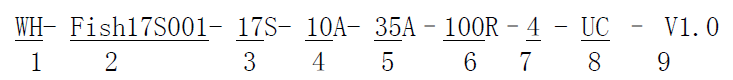
1 Huizhou Feiyu New Energy Technology Co., Ltd. logo;
2 Protection board model – (This protection board model is Fish17S001, other types of protection boards are marked, there is no limit to the number of characters in this item)
3. The number of battery strings supported by the required protection board – (this model of protection board is suitable for 17S battery packs);
4 Charging current value – 10A means the maximum support for continuous charging is 10A;
5 Discharge current value – 35A means maximum support for continuous 35A charging;
6 Balance resistance size – fill in the value directly, for example, 100R, then the balance resistance is 100 ohms;
7 Battery type – one digit, the specific serial number indicates the battery type as follows;
| 1 | Polymer |
| 2 | LiMnO2 |
| 3 | LiCoO2 |
| 4 | LiCoxNiyMnzO2 |
| 5 | LiFePO4 |
8 Communication method – one letter represents a communication method, I represents IIC communication, U represents UART communication, R represents RS485 communication, C represents CAN communication, H represents HDQ communication, S represents RS232 communication, 0 represents no communication, this product UC stands for UART+CAN dual communication;
9 Hardware version – V1.0 means the hardware version is version 1.0.
10 The model number of this protection board is: WH-Fish17S001-17S-10A-35A-100R-4-UC-V1.2. Please place the order according to this model number when placing bulk orders.
Also note:
1. When performing charge and discharge tests on the battery pack with the protective board installed, please do not use a battery aging cabinet to measure the voltage of each cell in the battery pack, otherwise the protective board and battery may be damaged. .
2. This protection board does not have a 0V charging function. Once the battery reaches 0V, the battery performance will be severely degraded and may even be damaged. In order not to damage the battery, the user should not charge the battery for a long time (the battery pack capacity is greater than 15AH, and the storage exceeds 1 Months) When not in use, it needs to be charged regularly to replenish the battery; when in use, it must be charged in time within 12 hours after being discharged to prevent the battery from being discharged to 0V due to self-consumption. Customers are required to have an obvious sign on the battery casing that the user regularly maintains the battery.
3. This protection board does not have reverse charging protection function. If the polarity of the charger is reversed, the protection board may be damaged.
4. This protective board shall not be used in medical products or products that may affect personal safety.
5. Our company will not be responsible for any accidents caused by the above reasons during the production, storage, transportation and use of the product.
6. This specification is a performance confirmation standard. If the performance required by this specification is met, our company will change the model or brand of some materials according to the order materials without further notification.
7. The short-circuit protection function of this management system is suitable for a variety of application scenarios, but it does not guarantee that it can be short-circuited under any conditions. When the total internal resistance of the battery pack and short-circuit loop is less than 40mΩ, the battery pack capacity exceeds the rated value by 20%, the short-circuit current exceeds 1500A, the inductance of the short-circuit loop is very large, or the total length of the short-circuited wire is very long, please test by yourself to determine whether This management system can be used.
8. When welding battery leads, there must be no wrong connection or reverse connection. If it is indeed connected incorrectly, the circuit board may be damaged and needs to be retested before it can be used.
9. During assembly, the management system should not directly contact the surface of the battery core to avoid damaging the circuit board. The assembly must be firm and reliable.
10. During use, be careful not to touch the lead tips, soldering iron, solder, etc. on the components on the circuit board, otherwise the circuit board may be damaged.
Pay attention to anti-static, moisture-proof, waterproof, etc. during use.
11. Please follow the design parameters and usage conditions during use, and the values in this specification must not be exceeded, otherwise the management system may be damaged. After assembling the battery pack and management system, if you find no voltage output or failure to charge when you power on for the first time, please check whether the wiring is correct.
Related products
10S 36V BMS 15A Lithium Battery for E-scooter
Model:Fish10S005


20S 60V/72V 60A CANBUS BMS for E-Motorcycles