

Product Description
This FY•X high quality 20S 72V 15A Hardware BMS for E-Unicycles is a protective plate solution specially designed by Huizhou Feiyu New Energy Technology Co., Ltd. for unicycle 20-string battery packs; it can be applied to different chemical propertiesLithium batteries, such as lithium ion, lithium polymer, etc. The protection board has strong load capacity, and the maximum continuous current can be 15A.
Functional characteristics
●20 batteries are protected in series;
●Charging and discharging voltage, temperature and other protection functions;
● Discharge alarm function;
● The switch controls the on/off function.
● Secondary overcharge fuse FUSE function (FUSE cannot be restored after fuse and needs to be replaced);
● Shut down to reduce power consumption.
● There is no discharge overcurrent and short circuit protection function. If overcurrent or short circuit occurs at the discharge port, the protection board may be burned out.
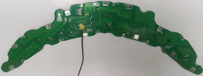
Physical reference picture

BMS front physical picture
Real picture of the back of BMS
Electrical Characteristic (Ta = 25 ℃.)
| Details | Min. | Typ. | Max | Error | Unit | ||
| Battery | |||||||
| Battery Gas | LiCoxNiyMnzO2 | ||||||
| Battery Links | 20S | ||||||
| Absolute Maximum Rating | |||||||
| Input Charging Voltage | 84 | ±1% | V | ||||
| Input Charging Current | 2 | 3 | A | ||||
| Output Discharging Voltage | 56 | 72 | 85 | V | |||
| Output Discharging Current | 15 | A | |||||
| Continuous Output Discharging Current | ≤15 | A | |||||
| Ambient Condition | |||||||
|
Operating Temperature |
-20 | 65 | ℃ | ||||
| Humidity (No Water-Drop) | 0% | RH | |||||
| Storage | |||||||
| Temperature | -40 | 85 | ℃ | ||||
| Humidity (No Water-Drop) | 0% | RH | |||||
| Protection Parameters | |||||||
| Over-Charge Voltage Protection | 4.250 | ±50mV | V | ||||
| Over-Charge Voltage Protection Delay Time | 0.5 | 1 | 3 | S | |||
| Over-Charge Voltage Protection Release | 4.150 | ±50mV | V | ||||
| Over-Discharge Voltage Protection | 2.800 | ±100mV | V | ||||
| Over-Discharge Voltage Protection Delay Time | 17 | 20 | 25 | S | |||
| Over-Discharge Voltage Protection Release | 3.000 | ±100mV | V | ||||
| Charging overcurrent protection | No such function | ||||||
| Discharge overcurrent protection, short circuit protection | No such function | ||||||
| Charging high temperature protection | 53 | 58 | 63 | ℃ | |||
| Charging high temperature protection Release | 50 | 55 | 60 | ℃ | |||
| Discharge over-temperature alarm (only alarm, does not shut down discharge) | 60 | 65 | 70 | ℃ | |||
| Discharge over-temperature alarm release | 55 | 60 | 65 | ℃ | |||
| Current Consumption | |||||||
| PowerConsumption on | 5 | mA | |||||
| SleepConsumption | 180 | 260 | uA | ||||
| ShipConsumption | 45 | 100 | uA | ||||
| Special instructions for low voltage of the entire battery pack | If the voltage of the entire battery pack is lower than 43V±1.5V, it cannot be charged. The battery pack needs to be charged directly. Only when the battery voltage is greater than 43.5V±1.5V can the BMS charge normally. | ||||||
FY•X high quality 20S 72V 15A Hardware BMS for E-Unicycles Function Description
1. Start up: Connect the ON/OFF terminal to the light touch switch string 200K resistor to B+), short press the switch for 1 second and then turn on the machine. The P+ and P- output ports have output and can discharge normally; please note that the time interval needs to be 5 after shutting down and then turning on the machine. seconds or more;
2. Shut down: Press and hold the switch for 3-5 seconds, the P+ and P- output ports will turn off the output, and the discharge will stop;
3. Secondary FUSE fuse condition: The charging circuit current for abnormal charging detection is 50~300mA or more, and the charging overvoltage or charging overtemperature conditions are met. The FUSE fuses with a delay of more than 10S. Once the FUSE fuses, it cannot be restored and needs to be replaced.
4. Cell overcharge protection and recovery: When the voltage of any cell is higher than the cell overcharge protection setting value, and the duration reaches the cell overcharge delay, the system enters the overcharge protection state and turns off the charging MOS. The battery cannot be charged.After the cell overcharge protection, when the voltage of all cells drops below the cell overcharge recovery value, the overcharge protection state is released.
5. Monomer over-discharge protection and recovery: After power-on, when the lowest node voltage is lower than the monomer over-discharge protection setting value, the alarm signal will be output after a delay of 3-6 seconds. When the continuous alarm time reaches 17-25 seconds, the system Enter the over-discharge protection state, turn off the discharge MOS, and cannot discharge the battery. If the over-discharge protection state continues for more than 30 seconds, the microcontroller will power off and enter deep sleep.
6. After the single unit over-discharge protection occurs, charging the battery pack can release the over-discharge protection state.
7. Charging temperature protection: BMS has a battery core temperature detection NTC, which is placed near the battery core for battery core temperature detection.
Charging high temperature protection and recovery
When the NTC detects that the temperature of the cell surface is higher than the set high temperature protection temperature, and the duration reaches the charging temperature after a delay of 3-6 seconds, the system enters the charging temperature protection state, the charging MOSFET is turned off, and the battery pack cannot be charged in this state. Charge.
When the temperature of the cell surface drops to the high temperature recovery set value, the BMS recovers from the high temperature state and can be recharged.
8. Discharge temperature alarm:
High discharge alarm and recovery
When the NTC detects that the temperature of the cell surface is higher than the set high temperature alarm temperature, and the duration reaches the discharge temperature after a delay of 3-6 seconds, the system enters the discharge temperature continuous alarm state, but the battery can still be discharged;
When the temperature of the cell surface drops to the high temperature recovery set value, the BMS recovers from the high temperature alarm state.
9. Alarm signals are disabled during charging
BMS principle block diagram
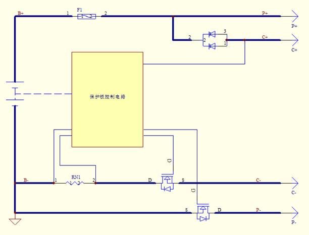
Protection principle block diagram
PCB size structure diagram
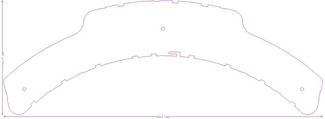
Dimensions 310.7*111.7mm Unit: mm Tolerance: ±0.5mm
Protection board thickness: less than 10mm (including components)
Port Definition
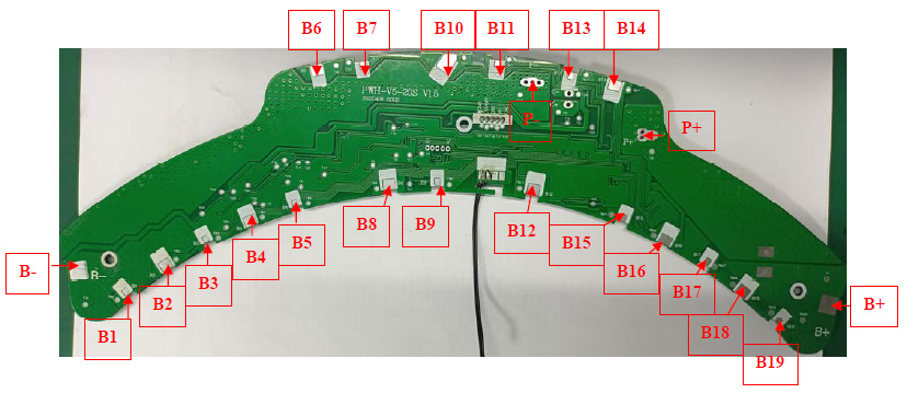
Protection board wiring diagram
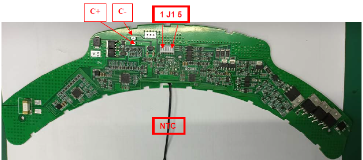
Protection board wiring diagram
Port definition description:
| Item | Details | |||
| C+ | Charging Positive Port. | |||
| P+ | Discharging Positive Port. | |||
| B+ | Connect to Positive Side of the pack. | |||
| B- | Connect to Negative Side of the pack. | |||
| P- | Discharging Negative Port. | |||
| C- | Charging Negative Port. | |||
| B1 | Connect to Positive Side of Cell 1. | |||
| B2 | Connect to Positive Side of Cell 2. | |||
| B3 | Connect to Positive Side of Cell 3. | |||
| B4 | Connect to Positive Side of Cell 4. | |||
| B5 | Connect to Positive Side of Cell 5. | |||
| B6 | Connect to Positive Side of Cell 6 | |||
| B7 | Connect to Positive Side of Cell 7 | |||
| B8 | Connect to Positive Side of Cell 8 | |||
| B9 | Connect to Positive Side of Cell 9 | |||
| B10 | Connect to Positive Side of Cell 10 | |||
| B11 | Connect to Positive Side of Cell 11. | |||
| B12 | Connect to Positive Side of Cell 12. | |||
| B13 | Connect to Positive Side of Cell 13. | |||
| B14 | Connect to Positive Side of Cell 14. | |||
| B15 | Connect to Positive Side of Cell 15. | |||
| B16 | Connect to Positive Side of Cell 16 | |||
| B17 | Connect to Positive Side of Cell 17 | |||
| B18 | Connect to Positive Side of Cell 18 | |||
| B19 | Connect to Positive Side of Cell 19 | |||
| J1 | 1 | CHG | CHG (charger insertion detection signal) | |
| 2 | UD | UD (combined signal alarm) a. Discharge over-temperature signal greater than 65 degrees OTD, b. Under-voltage signal DRR, c. Charging current abnormality detection signal CCK | ||
| 3 | ERR | ERR (overcharge signal alarm) | ||
| 4 | ON/OFF | ON/OFF (discharge switch: ON/OFF terminal connected to light touch switch string 200K resistor to B+) | ||
| 5 | PGND | PGND plus isolated power ground | ||
| NTC | temperature probe | |||
Battery connection sequence diagram
Process requirements
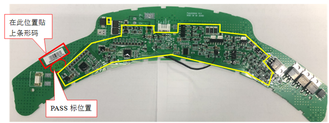
The requirements are as shown in the picture below: (The yellow box is the area for applying three-proof glue)
Precautions for connecting the protective board and the battery core
Warning: When connecting the protective plate to the battery cells or removing the protective plate from the battery pack, the following connection sequence and regulations must be followed; if operations are not performed in the required order, the components of the protective plate will be damaged, resulting in the protective plate being unable to protect the battery. core, causing serious consequences.
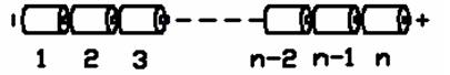
Preparation: According to the definition shown in Figure 9, connect the corresponding voltage detection cable to the corresponding battery core. Please pay attention to the order in which the sockets are marked.
Steps to install protective board:
Step 1: Weld the P- and C- wires to the corresponding positions of the protection board without connecting the charger and load.
Step 2: Connect the negative pole of the battery pack to B- of the protection plate;
Step 3: Connect B1, 2, 3, 4, 5, 6, 7, 8, 9, 10, 11, 12, 13, 14, 15, 16, 17, 18, 19 of the battery pack in sequence;
Step 4: Connect the positive terminal of the battery pack to B+ of the protection board;
Step 5: Connect the P+ of the battery pack;
Steps to remove the protective plate:
Step 1: Disconnect the positive terminal of all chargers\loads
Step 2: Remove the positive electrode of the battery pack to B+ of the protective plate;
Step 3: Remove B19, 18, 17, 16, 15, 14, 13, 12, 11, 10, 9, 8, 7, 6, 5, 4, 3, 2, 1, B of the battery pack in sequence -;
Step 4: Disconnect the negative terminal C-/P- of all chargers\loads
Additional notes: Please pay attention to electrostatic protection during production operations.
BOM list of main components
| Device type | model | encapsulation | brand | Dosage | Location | |
| 1 | Chip IC | PT6010EL32-AA | TQFP32 | China Resources Micro | 2PCS | U6,7 |
| 2 | Chip IC | N76E003AT20 | TSSOP20 | New Tang Dynasty | 1PCS | U5 |
| 3 | MOS tube | CRST060N10N | TO220 | China Resources Micro | 3PCS | M4,5,6,8 |
| 4 | NTC | NTC\100K\1%\4200\80mm | Tadpole type 28# PVC line | Jinglin | 1PCS | RT2 |
| 5 | PCB | Fish20S009(V5) V1.4 | 310.7*111.7*1.6mm | brand | 1PCS |
Ordering information

1.Huizhou Feiyu New Energy Technology Co., Ltd. logo;
2.Protection board model – (This protection board model is Fish20S009, other types of protection boards are marked, there is no limit to the number of characters in this item)
3.The number of battery strings supported by the required protection board – (this model of protection board is suitable for 17S battery packs);
4.Charging current value – 2A means the maximum support for continuous 2A charging;
5.Discharge current value – 15A means maximum support for continuous charging of 15A;
6.Balance resistance size – fill in the value directly, for example, 100R, then the balance resistance is 100 ohms;
7.Battery type – one digit, the specific serial number indicates the battery type as follows;
| 1 | Polymer |
| 2 | LiMnO2 |
| 3 | LiCoO2 |
| 4 | LiCoxNiyMnzO2 |
| 5 | LiFePO4 |
8.Communication method – one letter represents a communication method, I represents IIC communication, U represents UART communication, R represents RS485 communication, C represents CAN communication, H represents HDQ communication, S represents RS232 communication, 0 represents no communication, product UC Represents UART+CAN dual communication;
9.Hardware version – V1.0 means the hardware version is version 1.0.
10.The model number of this protection board is: FY-Fish20S009-20S-2A-15A-0-4-0-V1.4. Please place the order according to this model number when placing bulk orders.
Also note:
1. When performing charge and discharge tests on the battery pack with the protective board installed, please do not use the battery aging cabinet to measure the voltage of each cell in the battery pack, otherwise there may be
The protective board and battery may be damaged. .
2. This protection board does not have a 0V charging function. Once the battery reaches 0V, the battery performance will be seriously degraded and may even be damaged. In order not to
If the battery is damaged, the user needs to charge it regularly to replenish the power when not in use for a long period of time (battery pack capacity is greater than 15AH, storage exceeds 1 month); and
After being discharged during use, it must be charged in time within 12 hours to prevent the battery from being discharged to 0V due to self-consumption. Customers are required to have a clear label on the battery casing.
Display the user’s instructions for regular maintenance of the battery.
3. This protection board does not have reverse charging protection function. If the polarity of the charger is reversed, the protection board may be damaged.
4. This protective board shall not be used in medical products or products that may affect personal safety.
5. Our company will not be responsible for any accidents caused by the above reasons during the production, storage, transportation and use of the product.
6. This specification is a performance confirmation standard. If the performance required by this specification is met, our company will change some materials according to the order materials.
The model or brand of the material will not be notified separately.
7. This management system has no discharge overcurrent and short circuit protection functions. Please test by yourself to determine whether you can use this management system.
8. When welding battery leads, there must be no wrong connection or reverse connection. If it is indeed connected incorrectly, the circuit board may be damaged and needs to be retested to pass the test.
It can be used later.
9. During assembly, the management system should not directly contact the surface of the battery core to avoid damaging the circuit board. The assembly must be firm and reliable.
10. During use, be careful not to touch the lead tips, soldering iron, solder, etc. on the components on the circuit board, otherwise the circuit board may be damaged.
Pay attention to anti-static, moisture-proof, waterproof, etc. during use.
11. Please follow the design parameters and usage conditions during use, and the values in this specification must not be exceeded, otherwise the management system may be damaged. Place the battery pack
After being combined with the management system, if you find no voltage output or no power when powering on for the first time, please check whether the wiring is correct.
Note: After your company receives the prototype and specifications, please reply promptly. If there is no reply within 7 days, our company will regard your company as having recognized the specifications and send the prototype. If your order exceeds 50 PCS, you need to sign back the acknowledgment letter. If you do not sign back, our company will also regard your company as having approved this specification and send the sample machine. The pictures in the specification are of general models and may be slightly different from the sample delivered. Huizhou Feiyu New Energy Technology Co., Ltd. reserves the right of final interpretation of this specification.
Related Category
BMS for E-bike
BMS for E-scooter
BMS for E-Unicycles
BMS for Battery Rental Replacement
BMS for Automated Guided Vehicle
BMS for Storage Energy
BMS for E-Motorcycles
Send Inquiry
Related products
10S 36V 15A Hardware BMS for E-scooter
Model:Fish10S006


